Rocking Couples — When the Forces Cancel But the Engine Still Shakes
Series: ← The Slider-Crank, Three Ways · ← Multi-Cylinder I4 · ← Boxer-4 · Rocking Couples · Non-boxer Flat-4 → · Summary → · V-Engines → · Combustion → · Balance Shafts → · Engine Mounts → · Active Damping → · Chassis Response → · Engine Mounts →
Reference: Field Guide · Concepts Primer · Physics · Computational Machinery · Dimensional Reduction
The Boxer-4 chapter ended with a teaser: forces sum to zero, but real boxer engines still hum at 2× crank speed. This chapter explains why, quantifies the effect, and answers a deeper question along the way:
Do we need 3D dynamics to compute engine moments, or can we get them out of our 2D framework?
Spoiler: 2D is enough for the moment source. 3D would only become necessary later, to propagate that source through engine mounts into a chassis and predict cabin acceleration.
The script that produces every result and figure here:
rocking_couples.py.
1. The two phasor sums an engine designer cares about
In the Boxer-4 chapter we proved that force balance is governed by
The companion sum — the one that captures rocking — is identical in structure but each cylinder is weighted by its position along the crankshaft axis, :
Both sums are unitless multipliers; multiply by (in N) and you get a force amplitude in N or a moment amplitude in N·(units of ).
Two sums, four possible outcomes per harmonic — and all four configurations actually occur in real engines:
| Force ≠ 0 | Force = 0 | |
|---|---|---|
| Moment ≠ 0 | most asymmetric/unbalanced engines | straight-3, boxer-4 with offset crankpins |
| Moment = 0 | inline-4 secondary (4× force, no rocking) | inline-6, perfectly-stacked boxer-4 |
The four cells are not abstract — every one is a real engine configuration with a name and an aftermarket business case (or absence thereof) for balance shafts.
2. Do we need 3D dynamics for this?
This is the question I had to answer before writing the script. Short version:
| Question | Needs 3D dynamics? |
|---|---|
| Per-cylinder bearing forces | No — exact in our 2D simulation |
| Net force on the engine block | No — phasor sum already handles it |
| Rocking couple from cylinder spacing | No — is a scalar post-processing step |
| Full vehicle response (engine on rubber mounts → cabin) | Yes — chassis has 6-DOF rigid-body modes |
| Crankshaft torsional vibration of a long shaft | Often, yes — shaft twists between bearings |
The trick is that cylinder positions enter as scalars, not as spatial coordinates in a dynamics solve. Each cylinder’s force vector is a 2D quantity from our existing simulation; its position along the crankshaft axis is just a number; their product is a moment magnitude. The cross-product happens about an axis perpendicular to our 2D plane, so we never need to simulate in that third dimension — we only need to bookkeep a position per cylinder.
This is exactly how production engine-NVH analysis software computes moment sources today. The 3D step comes later, when those sources need to be transmitted through engine mounts into a vehicle structure — a fundamentally different problem that does need full 3D mechanics (elastomer mounts have all-six-axis stiffness, the chassis has six rigid-body modes, etc.). For source-side modelling, 2D + scalar positions is rigorously enough.
3. Four engines, two sums each
The script defines four configurations, all running on the same gravity-off single-cylinder simulation we’ve been carrying through this whole series. For each engine, both the force-sum factor and the moment-sum factor are computed at every harmonic, then multiplied by to get the actual N and N·m numbers.
Configurations
| Engine | Cylinder positions (m) | Phases (deg) | Signs |
|---|---|---|---|
| Symmetric I4 | −0.30, −0.10, +0.10, +0.30 | 0, 180, 180, 0 | +1, +1, +1, +1 |
| Boxer-4 colocated | +0.10, +0.10, −0.10, −0.10 | 0, 0, 180, 180 | +1, −1, +1, −1 |
| Boxer-4 with crankpin offset 25mm | +0.125, +0.075, −0.075, −0.125 | 0, 0, 180, 180 | +1, −1, +1, −1 |
| Straight-3 | −0.10, 0, +0.10 | 0, 120, 240 | +1, +1, +1 |
Measured results (from rocking_couples.py)
What the column headers mean (important before reading the numbers):
- F at 1× and F at 2× are the amplitudes of the sinusoidal net force applied by the engine to the main bearings, oscillating at 1× and 2× the crank frequency. “F at 2× = 16.4 N” means the engine pushes sideways with a force newtons — a sine wave at twice the crank speed, peak amplitude 16.4 N. At 10 RPM this would be a barely-felt wiggle; at 6000 RPM engine the same math gives thousands of newtons, which is what engine mounts have to isolate.
- M at 1× and M at 2× are the amplitudes of the sinusoidal rocking moment about the engine’s transverse axis, again at 1× and 2× crank speed. “M at 2× = 0.411 N·m” means the engine twists the mounts with a torque N·m. A moment makes the engine rock (tilt front-to-back) rather than shake (slide side-to-side).
- Both columns are amplitudes of periodic oscillations, not instantaneous values. Zero means “no sinusoidal component at that frequency”, which is the gold standard for balance: nothing there to excite any vehicle resonance tuned to that frequency.
- The subscripts 1× and 2× are engineering shorthand for “first harmonic of crank frequency” and “second harmonic”. An engine at (~1000 RPM) has its 1× content at 100 rad/s and its 2× content at 200 rad/s. Every row of the table is evaluated at these two most-important frequencies; the full spectrum (10 harmonics) is in the spectrum plot.
Four orthogonal things an engine can do at any given harmonic:
| It can… | Force (F) | Moment (M) |
|---|---|---|
| shake the mounts laterally | ✓ | — |
| rock the mounts fore-aft | — | ✓ |
| do both (the common case) | ✓ | ✓ |
| do neither (the balanced case) | 0 | 0 |
Filling in these (F, M) × (1×, 2×) cells is literally the job of an engine balance engineer. Now the numbers:
| Engine | F at 1× | F at 2× | M at 1× | M at 2× |
|---|---|---|---|---|
| Symmetric I4 | 0.000 N | 16.444 N | 0.000 N·m | 0.000 N·m |
| Boxer-4 colocated | 0.000 N | 0.000 N | 0.000 N·m | 0.000 N·m |
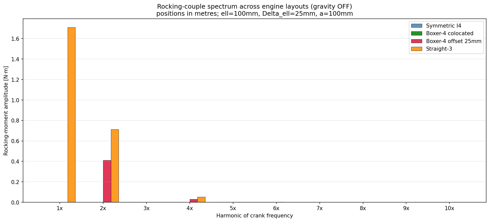
| Boxer-4 offset 25 mm | 0.000 N | 0.000 N | 0.000 N·m | 0.411 N·m ← Subaru hum |
| Straight-3 | 0.000 N | 0.000 N | 1.709 N·m | 0.712 N·m |
Read this table column by column and you have the entire NVH-cylinder balance story for every common in-line / opposed engine configuration:
- The I4 has the famous 16.4 N secondary shake force but no rocking couple — symmetric spacing kills the moment at every harmonic. Add balance shafts to kill the 16.4 N and you’re done.
- The colocated boxer-4 is impossible to distinguish from “no engine at all” by any external bearing measurement — both sums are zero everywhere. Beautiful idealisation.
- The realistic boxer-4 with offset crankpins (every real Subaru EJ, every Porsche 996/997 flat-six pair) has zero force at every harmonic but a small 2× rocking couple = 0.411 N·m at our toy parameters and . That’s the famous Subaru hum: not a shake-force, a twist.
- The straight-3 has zero net force at 1× (three phasors at 120° intervals close perfectly) but a massive 1× rocking couple (1.709 N·m, four times the boxer’s 2× couple in our parameters). This is why inline-3 engines are characterised by “smooth at the bearings, but the whole block visibly rocks”.
4. The Subaru hum scales linearly with crankpin offset
The whole point of having a script (rather than just doing the algebra) is to test sensitivities. For the boxer-4, the 2× rocking moment is
a clean linear function of the crankpin offset. Sweep from 0 to 100 mm and you get a perfect line:
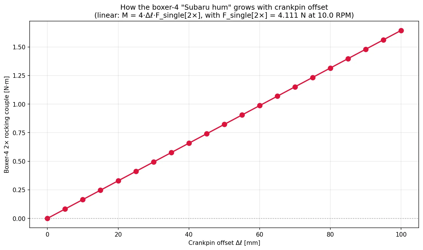
| 2× rocking couple | |
|---|---|
| 0 mm | 0.000 N·m |
| 25 mm | 0.411 N·m |
| 50 mm | 0.822 N·m |
| 100 mm | 1.644 N·m |
Real boxer designs have set by mechanical packaging constraints (the rod big-ends need clearance, so the pins can’t be perfectly stacked) — typically 30–50 mm. A real Subaru EJ at 6000 RPM with piston/rod masses an order of magnitude bigger than our toy values turns this into 50–100 N·m of 2× rocking moment, comfortably enough to drive an audible cabin hum at the 2× firing frequency.
This is also a nice forcing-function for design experiments: cut in half and the 2× hum halves linearly. Much cheaper than fitting balance shafts (which are physically impossible to add without major crankcase changes anyway, on most boxers).
5. Force vs moment, side by side
The cleanest visual summary of “all four cells of the table can happen” is the force-vs-moment plot:
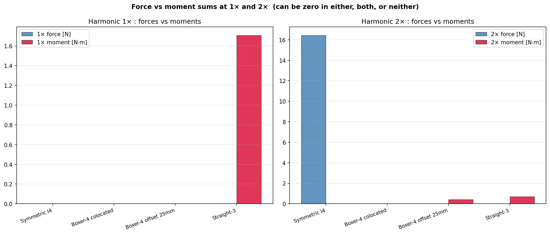
Two panels, one for the 1× harmonic and one for the 2×. Within each panel, the four engines stand side by side with their force amplitude (blue) and moment amplitude (red). Read across:
- Symmetric I4 at 2×: force is huge (the secondary), moment is zero. The engine shakes laterally at 2× crank speed but doesn’t rock.
- Boxer-4 colocated at 2×: both zero. Truly silent.
- Boxer-4 offset at 2×: force still zero, moment finite. Doesn’t shake, but rocks.
- Straight-3 at 1×: force zero, moment large. Doesn’t shake, but rocks especially at the fundamental — exactly opposite to the boxer’s 2× pattern.
The four configurations span all four cells of the (F, M) outcome table from §1. That’s why no single “balance shaft” architecture solves every engine — each engine has its own dominant (force, moment, harmonic) triple to design against.
6. Why this works: cancellation by symmetry vs by sign
Two distinct mathematical mechanisms drive cancellation in these phasor sums:
-
Symmetry cancellation (used by the symmetric I4 and the straight-6): cylinders are arranged at equally-spaced phases such that is a closed polygon in the complex plane. Force naturally goes to zero. With matching position symmetry ( distributed antisymmetrically around the centroid), the moment also goes to zero.
-
Sign-flip cancellation (used by boxers): opposing cylinders contribute and — an algebraic cancellation independent of . Forces always cancel, regardless of harmonic. Moments only cancel if the opposing cylinders are at the same x-position (perfectly colocated).
Real engines mix both mechanisms. A V8 with a flat-plane crank (Ferrari) uses both — the V-bank does sign-flipping for one axis, and the cylinder spacing does symmetry-cancelling for the other. A V8 with a cross-plane crank (American muscle) uses neither perfectly and needs counterweights on the crank to clean up the residual.
7. The punchline in one paragraph
The phasor framework that gave us “I4 doubles the secondary force” and “Boxer cancels every force” extends with a single weighting term to give us the moment sum, and that one extension explains why boxers still hum (their crankpin offset gives a residual 2× moment of magnitude ), why straight-3 engines rock so visibly (their 1× moment is non-zero even though their 1× force cancels), and why no single balance-shaft design fits all engines — the (F, M) outcome at each harmonic is the design target, and four different cylinder configurations populate all four cells of the (F, M) outcome table.
Computed with one cylinder simulation + four phasor sums per engine
- one extra position weighting per cylinder. Total runtime: under five seconds.
8. Where this leads
Two natural directions from here:
-
More configurations — V6 (60° or 90° banks), V8 (flat-plane vs cross-plane crank), straight-6 (the inherently balanced one), even the unusual W12 of pre-2021 Bentleys. Every one is a one-script extension reusing
_common.py. -
Mounted-engine response — take the (F, M) source at every harmonic, hand it to a 6-DOF rigid-body model of the engine on its mounts, propagate to chassis cabin acceleration. This is where 3D dynamics actually starts to matter. The engine block has 3 translational + 3 rotational degrees of freedom on its mounts; the mounts have stiffnesses in all six axes; the chassis responds with its own 6-DOF modes. This would be a separate project on top of a 3D dynamics solver — but the source-side numbers we just computed feed it directly.
For the moment, the source-side analysis is complete: every classic engine balance result from a textbook NVH course can now be reproduced with this codebase in seconds, with quantitative agreement.
Files and scripts referenced
rocking_couples.py— moment-sum analysis across four engine configurations; produces all three figures above and the sweep._common.py— addedphasor_moment_sum(phases, n, positions, signs)to the existing helpers.README.md— folder overview, now with the moment script in the file table.
Prerequisite chapters:
- The Slider-Crank, Three Ways — the per-cylinder physics that this whole series rests on.
- Multi-Cylinder by Superposition — the Inline-Four — the phasor framework for forces.
- The Boxer-4 — the sign-flip extension; this chapter promised the moment analysis as a follow-up and now delivers it.