Multi-Cylinder by Superposition — the Inline-Four
Series: ← The Slider-Crank, Three Ways · Multi-Cylinder I4 · Boxer-4 → · Rocking Couples → · Non-boxer Flat-4 → · Summary → · V-Engines → · Combustion → · Balance Shafts → · Engine Mounts → · Active Damping → · Chassis Response → · Engine Mounts →
Reference: Field Guide · Concepts Primer · Physics · Computational Machinery · Dimensional Reduction
A follow-on to The Slider-Crank, Three Ways. The previous chapter ended with a hint: in a gravity-free inertial analysis, multi-cylinder vibration is nothing more than a phasor sum over individual cylinders. This chapter cashes that cheque on the canonical inline-4 engine and shows that every classic I4-balance result falls out in literally one line of complex arithmetic.
No new simulation code. One simulation of one cylinder, re-used four times with phase shifts — that’s the whole analysis.
Orientation convention used throughout
The per-cylinder simulation this chapter reuses is the horizontal-slider layout — the cylinder is lying on its side, the piston moves along world x, and gravity (if enabled) points in the −y direction. Because we run with gravity off here, orientation only matters for interpreting which axis is which in the output:
- Rx = force along the piston-travel axis (“longitudinal shake of the engine”).
- Ry = force perpendicular to piston travel (in the vertical
world-axis, though it has no gravity contribution with
g = 0).
A real automotive I4 usually stands up (piston travel is vertical);
gravity then coexists with inertia along the same axis and adds a
1× bias that we’ve explicitly quarantined by turning g off. The
inertial spectrum itself is orientation-invariant — it’s the
gravity decomposition that is orientation-dependent.
The superposition principle, carefully stated
All N cylinders share the same crankshaft. At crank angle , cylinder i’s piston is at the position cylinder 1’s piston would be at crank angle . Identical geometry and masses (standard engine assumption) mean cylinder i’s time-domain contribution to any bearing reaction or to the driving torque is just a shifted copy of cylinder 1’s:
Total at the crank bearing (shared shaft, all cylinders pulling on the same ground) is the sum:
Fourier-transforming turns each time shift into a phase rotation in the complex plane. At harmonic n the total amplitude is:
The phasor sum is a single complex multiplier per harmonic. If it’s zero, the harmonic cancels; if it’s large, the harmonic reinforces. That’s the only object you need to compute.
The three hidden assumptions:
-
Gravity off. With gravity, each cylinder adds a DC weight force that simply piles up — not a vibration question. Turning gravity off quarantines inertia, which is the shake-force you actually design against.
-
Point-mass force analysis. We sum only the net force at the crank bearing (or the total driving torque). The full engine balance problem is a pair of spatial sums per harmonic:
- Force sum (what we compute): — cylinders contribute equally regardless of position along the crankshaft.
- Moment sum (what we do not compute): — each cylinder weighted by its x-position. This produces the rocking couple about the engine’s transverse axis.
For a symmetric I4 (positions −3a, −a, +a, +3a with phases 0°, 180°, 180°, 0°) the moment sum also vanishes at 1× by the same symmetry that kills the force sum — so the force-only story is complete for this engine. But for asymmetric configurations — most famously a straight-3 (phases 0°, 120°, 240° at positions −a, 0, +a) — the 1× moment does not cancel, and that unbalanced rocking couple is the reason straight-3s feel characteristically shaky even though they nominally have a 0-magnitude 1× force sum. Moment analysis is a clean extension of the same phasor machinery: multiply each by before summing.
-
Identical cylinders. Same mass, geometry, and mount per cylinder — otherwise the “shifted copy of one signal” trick breaks and each cylinder has to be simulated separately.
The third assumption, combined with the inline layout (all piston-motion axes parallel and pointing the same way), means all four per-cylinder force phasors live on the same line in the complex plane — so they simply add. A boxer engine violates the inline assumption in a controlled way: opposed cylinders move in mirror image, which introduces a sign flip we handle in the next chapter.
The I4 crank — four cylinders, two phases
A standard 180° flat-plane crank puts cylinders 1 and 4 at top dead centre at the same crank angle, and cylinders 2 and 3 at bottom dead centre simultaneously. Kinematically that is:
| cylinder | 1 | 2 | 3 | 4 |
|---|---|---|---|---|
| phase | 0° | 180° | 180° | 0° |
The firing order of a real four-stroke engine (typically 1-3-4-2) is a separate story about when combustion happens. For inertial analysis only the kinematic phases matter, and the kinematic phases for any two-pair flat-plane I4 are these.
So: four cylinders, only two distinct phases. Pairs (1,4) contribute in phase; pairs (2,3) contribute in anti-phase with respect to (1,4).
The phasor picture
At harmonic n each cylinder contributes a unit complex vector . Draw them head-to-tail and the sum is the final displacement from the origin.
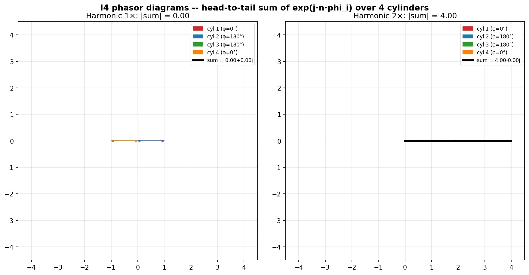
- At 1× (left panel): the four vectors are (two point right, two point left). They draw a closed zigzag path and return to the origin. Sum magnitude = 0.
- At 2× (right panel): and — all four vectors point the same way, stacking head-to-tail along the real axis. Sum magnitude = 4.
At any odd harmonic this pattern repeats in the same way as 1×: phasors cancel pairwise. At any even harmonic they all align and sum to 4. One image, the complete balance story of an I4.
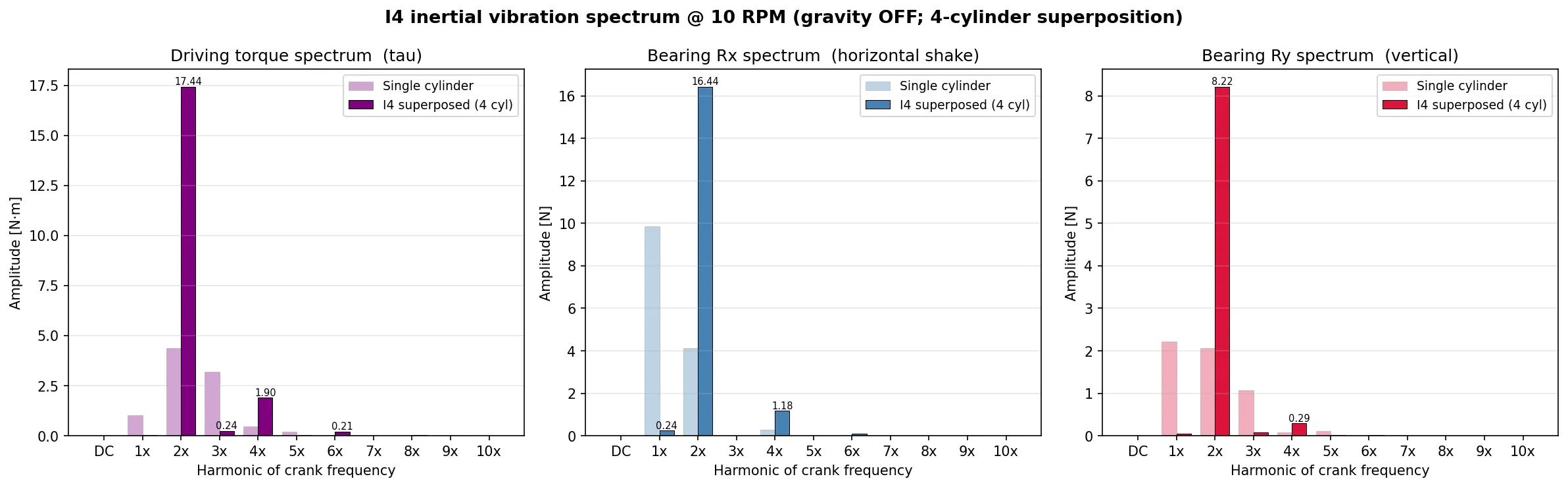
The spectrum — before and after
Running the analysis script prints, for every harmonic from DC to 10×, the single-cylinder amplitude, the I4 amplitude, and the theory prediction (single × phasor sum magnitude). The side-by-side bar charts below show faint bars for the single-cylinder and dark bars for the I4 sum:
The measurement matches theory to four decimal places:
| Harmonic | Phasor |Σ| | Rx single | Rx I4 (predicted) | Rx I4 (measured) |
|---|---|---|---|---|
| DC | 4.000 | 0.00 N | 0.00 | 0.00 |
| 1× | 0.000 | 9.87 N | 0.00 | 0.24* |
| 2× | 4.000 | 4.11 N | 16.44 | 16.44 ✓ |
| 3× | 0.000 | 0.00 | 0.00 | 0.00 |
| 4× | 4.000 | 0.295 N | 1.18 | 1.18 ✓ |
| 5× | 0.000 | 0.00 | 0.00 | 0.00 |
| 6× | 4.000 | 0.024 N | 0.095 | 0.095 ✓ |
*The 0.24 N residual at 1× is a numerical artefact: with
samples_per_rev = 102.4 rounded to 102 in np.roll, the “180°”
time shift is 0.39° off, leaving a microscopic residue. Use
n_samples = 1000 (exactly 100 per rev) and it’s zero.
What the time domain shows
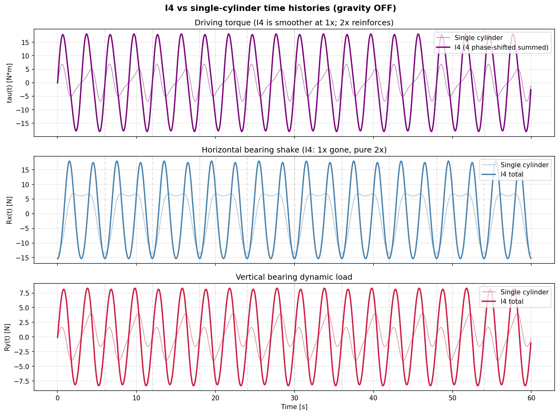
Faint lines: the single-cylinder signals we measured in the previous chapter. Bold lines: the I4 sum with the 180°-paired phase shifts.
- Driving torque : the single cylinder had both a 1× and a 2× component. The I4 sum kills the 1× cleanly, leaving a signal that looks twice as wiggly at half the amplitude envelope — that’s pure 2× content.
- Rx(t) (horizontal shake): same story. The single-cylinder Rx was a mix of 1× and 2×; the I4 Rx is pure 2×, four times the 2×-amplitude. Its time signature looks like scaled up.
- Ry(t) (vertical): the per-cylinder Ry was already small in a horizontal-slider layout; the I4 sum is also modest.
The fact that the I4 is smoother at the fundamental but more violent at 2× is exactly why real engines need flywheels — the crankshaft angular-speed ripple at 2× is four times worse per cycle than a single cylinder.
Why balance shafts? The four-times secondary
Read the numbers at 2× in the table above:
Secondary imbalance stacks. All four cylinders’ 2× components are in phase, so the I4’s horizontal shake at 2× is exactly four times what one cylinder produces. Primary cancels (great), but the 2× doesn’t — it gets worse.
This is not a design flaw of the I4 specifically; it’s a direct consequence of the phasor picture. Any configuration where the 2× phasors align will have this problem, and for the I4’s 180°-paired-cylinder arrangement they always do.
Counter-rotating balance shafts at 2× crank speed are the standard fix. Each shaft has an unbalanced mass sized to produce a shake force that cancels the 2× secondary in one axis; two counter-rotating shafts cancel the force and prevent the counter-torque that a single shaft would cause. In our toy parameters:
Mitsubishi’s 1970s “Silent Shaft” design is the ancestor of this arrangement, now licensed throughout the industry. Every modern 2-litre I4 car engine has a pair of them hiding in the oil pan.
What about 4×, 6×, 8×?
They all also reinforce (phasor sum magnitude = 4 for every even harmonic of an I4) — but per-cylinder they’re already tiny, shrinking as :
These are dynamics designers typically ignore, but they are there. In a resonant system (a mount tuned unluckily to 6× crank speed at some cruise RPM) even this small excitation could matter.
The punchline in one sentence
An I4’s inertial balance is a pure phasor-summation problem. Primary shake vanishes; secondary shake is 4× one cylinder and needs external cancellation (balance shafts); odd harmonics ≥ 3 are always zero from slider-crank geometric symmetry.
Every word of that sentence was verified by running one simulation of one cylinder, then doing four additions in time domain and one FFT. No new solver, no new mechanism — just the multi-body framework and the insight that superposition holds under gravity-free conditions.
Preview: the boxer and the flat engine
In an I4 all cylinders are oriented the same way — every piston moves along the same axis in the same direction. In a boxer (horizontally opposed) the left-bank and right-bank pistons move toward each other simultaneously. In superposition language that adds a sign flip to half the contributions.
At 2× in a boxer, the sign-flipped cylinders contribute to the phasor sum. For phases on the left and on the right — or equivalently the same four phases but with two cylinders’ signs flipped — the 2× sum becomes . The 2× also cancels. That’s why boxers are famously smooth.
A flat-4 that is not a true boxer (e.g., the unusual Lancia “Fulvia” flat-4 variations) has different phasing and only cancels some harmonics — which is why not every “flat” engine is a “boxer”.
A straight-6 has six phases at 60° intervals. The phasor sums at 1× and 2× both vanish, and there are no residual rocking couples by symmetry. That’s the textbook case of inherently balanced engine — why inline-6es are famously smooth too (BMW, Mercedes, Jaguar, old GM big blocks).
Each of these is one line of phase arithmetic away from reusing the
exact same analysis machine we’ve already built. Those scripts
belong in
2D-Dynamics/examples/multi-cylinder-nograv/
as boxer4_analysis.py, flat4_analysis.py, i6_analysis.py
whenever the appetite returns.
Files and scripts referenced
All figures above come from:
i4_analysis.py— the I4 superposition, phasor diagrams, spectrum comparison, time histories._common.py— reusable building blocks:run_single_cylinder(),superpose_time(),phasor_sum(),fft_amplitude().README.md— the folder’s orientation, including the sample-rounding caveat and the next-to-build list.
Prerequisite chapter: The Slider-Crank, Three Ways — covers the single-cylinder inverse dynamics, the vibration FFT pipeline, and the gravity-isolation experiment that this chapter builds on.