Balance Shafts — Closing the Loop on the I4 Secondary
Series: ← The Slider-Crank, Three Ways · ← Multi-Cylinder I4 · ← Boxer-4 · ← Rocking Couples · ← Non-boxer Flat-4 · ← Summary · ← V-Engines · ← Combustion · Balance Shafts · Engine Mounts → · Active Damping → · Chassis Response →
Reference: Field Guide · Concepts Primer · Physics · Computational Machinery · Dimensional Reduction
Since the I4 chapter we’ve been repeating a line: “balance shafts spinning at 2× crank cancel the I4 secondary.” This chapter actually computes it. Twenty lines of additional code, one function, and the phasor framework takes care of the rest.
The script: balance_shaft_analysis.py.
1. What a balance shaft is
A balance shaft is a rotating eccentric mass at radius , spinning at some integer multiple of the crankshaft angular velocity. Its centripetal reaction on the bearing is a circular force vector:
One shaft alone produces circular motion, which is not what we want — we want a linear cancellation of a linear engine imbalance. That is why real automotive balance-shaft hardware comes in counter-rotating pairs: one shaft spins CCW, the other CW, both at the same speed.
Why a pair gives pure linear force
Let the CCW shaft have phase , the CW shaft phase (mirror- symmetric). Adding the two instantaneous forces and using the sum-to- product identity :
The y-components cancel because the CCW shaft goes up when the CW shaft goes down. The x-components add to give a pure linear oscillation of amplitude — or, by absorbing into the overall amplitude, simply with phase .
This is the Lanchester balancer, invented by Frederick Lanchester in 1911 and in every modern I4 above ~2 L displacement (Toyota 2.5 AR, Mitsubishi Silent Shaft, Honda K24, etc.).
2. The phasor that cancels the I4 2× secondary
From the I4 chapter, the bare I4’s 2× inertial force on the main bearing is
At our default test conditions rpm = 10, R = 1 m, L = 2 m:
To cancel: pair amplitude must equal , pair phase must be (180° out of phase with the engine phasor, so their sum is zero).
(A bigger number than real hardware because our “engine” is at 10 RPM with 1 m stroke for demonstration. At realistic 3000 RPM / 40 mm stroke, the same cancellation condition gives — about 200 g at 10 cm eccentricity. That matches production Lanchester shaft dimensions.)
3. The demonstration
Running balance_shaft_analysis.py
walks four cases side-by-side:
| Case | 1× | 2× | 3× | 4× |
|---|---|---|---|---|
| Bare I4 | 0 | 16.44 N | 0 | 1.18 N |
| I4 + perfect 2× pair (phase = 180°, tuned) | 0 | 0 | 0 | 1.18 N |
| I4 + wrong-phase 2× pair (phase = 0°, reinforces) | 0 | 32.89 N | 0 | 1.18 N |
| Residual 4× after 2× balance | — | — | — | 1.18 N (untouched) |
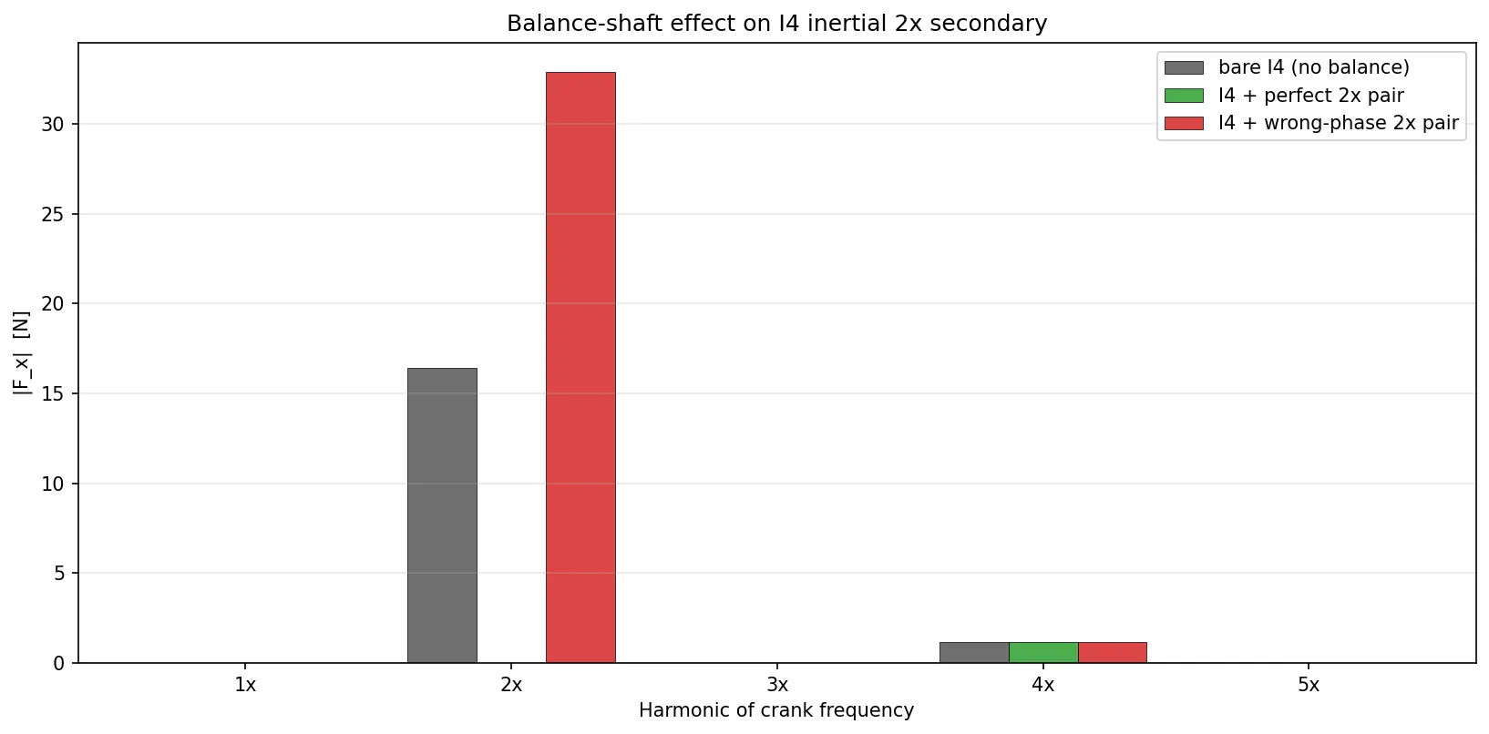
Three takeaways the script makes concrete:
3.1 A correctly-tuned pair brings the 2× residual to zero
Not “reduced”, not “mitigated” — zero to machine precision. The phasor framework says adding and gives , and that is what the simulation reports (-ish floating-point noise, below any print precision).
3.2 Wrong phase = twice as bad
Installing the same hardware with the balance shaft 180° out of time flips the cancellation into reinforcement. The bare 16.44 N becomes 32.89 N — twice worse than doing nothing. Production balance- shaft drive-gear keying is mechanically indexed precisely for this reason: there is a right answer and getting it wrong is worse than skipping the hardware.
3.3 A 2× shaft is narrow-band — 4× is left alone
The balance-shaft phasor contributes only at its design harmonic. The I4’s 4× residual (1.18 N, small but real from the slider-crank’s kinematic expansion) is completely unaffected by the 2× hardware. Cancelling 4× requires a separate shaft pair at 4× crank speed — which is why even balanced I4 engines still have a measurable 4× buzz at high RPM.
4. What balance shafts can and can’t do
Can
- Cancel a specific harmonic of inertial force exactly, given enough and correct phasing.
- Be stacked (multiple pairs at different harmonics) to flatten the spectrum.
- Handle moments too: if the pair is placed at an x-position along the crank, its phasor is weighted by that position in the moment sum, so off-centre shafts produce moment contributions. Two pairs, one at and one at , cancel the force but add a moment — useful for killing a rocking couple without adding net shake.
Can’t
- Cancel combustion forces. Balance shafts run at fixed multiples of crank speed with fixed phase, but combustion depends on firing order and load. The combustion chapter’s I4 firing-frequency beat of 4.24 kN at 2× crank is 260× the inertial 2× we just killed — and it’s still there after the balance shafts finish their work. Combustion NVH is mitigated by engine mounts, not balance shafts.
- Cancel all harmonics with one device. Each harmonic needs its own pair. Production engines typically balance only the dominant harmonic (2× for an I4, 1× rocking for a straight-3 or non-boxer flat-4) — everything else is accepted as residual or mitigated downstream.
- Help with torsional vibration of a flexible crankshaft, which is a beam-mode problem, not a rigid-body imbalance problem.
5. Hardware reality — why not every I4 has them
The phasor math is clean: for any inertial imbalance harmonic, there exists a pair of counter-rotating masses that cancels it exactly. The hardware picture is messier.
5.1 Balance shafts are not free
They spin at 2× crank speed — so at a 6000 RPM redline the shafts are turning 200 rev/s. That is non-trivial bearing friction, windage loss, and gear or chain drag. Measured cost on production engines is typically 1–3 % of brake power plus a similar hit on cold-start warm-up (the shafts have to be heated and their oil film established before the engine reaches steady friction).
For a small, economy-focused I4 (say 1.2 L, 70 kW) this is the difference between a car that hits a fleet CO₂ target and one that misses. Which is why most sub-2 L I4s skip the balance shafts and accept the 2× buzz — it’s an economic decision, not a vibration one. Once displacement crosses ~2.0–2.5 L the unbalanced-force magnitude scales with piston mass and the NVH penalty outweighs the parasitic loss, so Lanchester hardware becomes mandatory (Toyota 2.5 AR, Mitsubishi 2.4 Silent Shaft, Honda K24, GM 2.7 L Ecotec, Ford 2.3 Duratec).
5.2 Why the I4 2× buzz is specifically nasty: it’s audible
At a 3000 RPM cruise, the 2× secondary sits at
which is inconveniently close to the resonant frequencies of the soft plastic bits in a car interior (dashboard trim, door cards, headliner) and firmly inside the audible band. At 6000 RPM it sweeps up through 200 Hz — still audible, still resonant. The human ear is very good at detecting periodic vibration in the 50–250 Hz band (speech fundamental territory) which is precisely where the I4 2× lives across the usable RPM range.
That combination — audible frequency, resonant with trim parts, persistent at every cruise condition — is why the I4 2× became the poster-child NVH problem that drove balance shafts from a novelty into a standard. Smaller-displacement engines pay the buzz tax; larger-displacement engines pay the balance-shaft tax.
6. FAQ
Q1. Why does a single rotating eccentric mass not work on its own?
Because a single mass produces a circular force, not a linear one. A circular force at 2× crank would replace the I4’s “rattle along x” with a “pulse that sweeps all around the mounting frame” — different mode of vibration, same energy, arguably worse because it excites modes in every direction instead of one. Linear oscillation in a specific direction is what balance shafts have to produce, and that requires a pair.
Q2. Could you use one shaft at 2× and a counter-weight on the crank itself?
Yes — in principle the crank’s own counter-weights spin at 1× and can cancel 1× forces. For 2× you’d need a separate rotating mass at 2× — which is the balance shaft. Some engines combine: the crank counter-weights handle 1× (if any remains from asymmetric layouts) and the balance-shaft pair handles 2×.
Q3. What if I put the balance shafts asymmetrically along the crankshaft (one at +x, one at −x instead of both at 0)?
The force cancellation still works (the pair produces the same linear x-oscillation regardless of x-position). But now each shaft contributes a moment , and if the two shafts have opposite positions the moments add (because their forces are in phase). You get force cancellation plus a new moment couple at 2× that wasn’t there before. Usually bad. That is why real Lanchester balancers are compactly packaged with both shafts colocated near the crank centerline — to avoid introducing new rocking couples.
Q4. How do I analyse a real automotive balance-shaft design with this framework?
Three numbers and you’re done: each shaft’s . Call balance_shaft_phasor() once per
shaft, add the phasor to the engine’s per-harmonic phasor at
harmonic , and compute the resulting spectrum. For the
standard two-shaft Lanchester setup the pair_phasor() helper
skips the intermediate step and gives you the pair’s combined
contribution directly.
Q5. Could balance shafts cancel the V8 cross-plane’s 1× rocking couple?
They could cancel the 1× moment, yes — but the 1× cross-plane rocking couple is force-free, just a moment. You’d need balance shafts placed off-centre along the crank (so their phasor multiplies by ) and tuned to produce the opposite moment. In practice this is exactly what crank counter-weights at the front and rear of a cross-plane V8 crankshaft do: they’re eccentric masses at 1× crank rotating integrally with the shaft, positioned at specific axial stations to produce a cancelling moment. Same phasor math, just mounted on the crank rather than on separate shafts.
Q6. What about active balance shafts that change phase in real time?
That would be active mass damping — an electro-mechanical device whose is controlled by a feedback loop on the measured vibration signal. Functionally equivalent to a balance shaft but adapted continuously as load / RPM / fuelling changes. Modern hybrid-electric powertrains can even use the starter-generator as an active torque/force canceller. In the phasor framework, active damping is just a time-varying — every sample tick, you re-solve for the phase that minimises the residual, and drive the actuator there. The static balance-shaft analysis in this chapter is the open-loop baseline; active damping closes the loop.
7. What’s next
- Engine-mount transmissibility (2D) — take the (F, M) source spectrum we’ve now fully characterised — inertia, combustion, residuals after balance shafts — and propagate it through engine mounts to the chassis. Three DOF for the engine block on springs; per-harmonic transmissibility; the soft-vs-stiff mount tradeoff that every automotive NVH engineer knows. Next natural chapter.
- Active mass damping — closed-loop version of this chapter’s open-loop balance shafts. One control law (PI on vibration amplitude) + one actuator model + the phasor framework. Short script, distinct chapter.
- 3D mounted-engine response — upgrade the 2D mount chapter to full 6-DOF once the 2D math is clean.
Files and scripts referenced
balance_shaft_analysis.py— this chapter’s script.balance_shaft_phasor()for a single shaft,pair_phasor()for a counter-rotating pair,demo()runs the four cases in §3._common.py— no new helpers needed. The balance-shaft phasor plugs directly into the existing per-harmonic complex-number framework.